|
| FLAT STEEL LIFTING SYSTEM |
| |
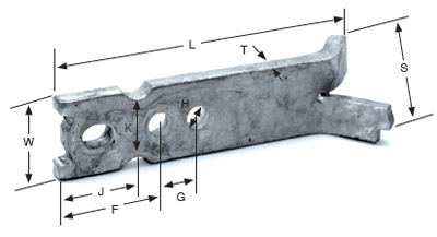
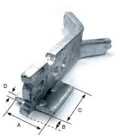
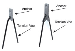
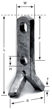
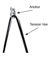
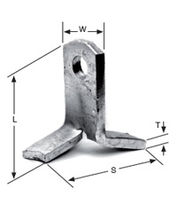
ERECTION ANCHOR
Designed to edge lift panel to vertical position. Welded shear plate eliminates need for shear bars.
CAPACITIES
See table on next page for capacities in shear and tension.
|
 |
|
| 2.5 |
F EA 02.5 080 |
203 |
50 |
10 |
46 |
35 |
14 |
29 |
57 |
70 |
| 5 |
F EA 05 105 |
267 |
64 |
16 |
64 |
46 |
20 |
32 |
81 |
85 |
| 7.5 |
F EA 07.5 128 |
325 |
95 |
16 |
62 |
62 |
25 |
44 |
102 |
127 |
| 10 |
F EA 10 128 |
325 |
95 |
20 |
81 |
65 |
25 |
44 |
102 |
127 |
|
 |
| 2.5 |
F EA 02.5 080 S |
64 |
20 |
76 |
6 |
| 5 |
F EA 05 105 S |
64 |
32 |
76 |
10 |
| 7.5 |
F EA 07.5 128 S |
76 |
41 |
76 |
10 |
| 10 |
F EA 10 128 S |
76 |
41 |
76 |
10 |
|
|
 |
|
|
Concrete Strength [] |
| Nominal System Capacity |
Rebar Size |
15 |
20 |
27 |
35 |
41 |
|
|
Length of rebar before bending [mm] |
| 2.5 Ton |
10 |
787 |
635 |
558 |
482 |
457 |
| 5 Ton |
12 |
1041 |
838 |
736 |
660 |
609 |
| 7.5 Ton |
16 |
1295 |
1066 |
914 |
812 |
736 |
| 10 Ton |
19 |
1549 |
1270 |
1092 |
990 |
889 |
|
|
| |
| ERECTION ANCHOR LOAD CHART |
2.5-Ton Ring Clutch
(2.5 Ton Anchor) |
|
|
|
|
|
| 2.5T |
FEA02.5080 |
127 |
958 kg |
1762 kg |
1814 kg |
| 2.5T |
FEA02.5080 |
140 |
959 kg |
1814 kg |
1814 kg |
| 2.5T |
FEA02.5080 |
152 |
1149 kg |
1814 kg |
1814 kg |
| 2.5T |
FEA02.5080 |
178 |
1308 kg |
1814 kg |
1814 kg |
| 2.5T |
FEA02.5080 |
203 |
1426 kg |
1814 kg |
1814 kg |
| 2.5T |
FEA02.5080 |
229 |
1562 kg |
1814 kg |
1814 kg |
| 2.5T |
FEA02.5080 |
254 |
1644 kg |
1814 kg |
1814 kg |
| 2.5T |
FEA02.5080 |
279 |
1762 kg |
1814 kg |
1814 kg |
| 2.5T |
FEA02.5080 |
305 |
1814 kg |
1814 kg |
1814 kg |
5-Ton Ring Clutch
(5 Ton Anchor) |
|
|
|
|
|
| 5T |
FEA05105 |
152 |
1360 kg |
2351 kg |
3628 kg |
| 5T |
FEA05105 |
178 |
1431 kg |
2728 kg |
3628 kg |
| 5T |
FEA05105 |
203 |
1562 kg |
3129 kg |
3628 kg |
| 5T |
FEA05105 |
229 |
1648 kg |
3531 kg |
3628 kg |
| 5T |
FEA05105 |
254 |
1744 kg |
3628 kg |
3628 kg |
| 5T |
FEA05105 |
279 |
1789 kg |
3628 kg |
3628 kg |
| 5T |
FEA05105 |
305 |
1814 kg |
3628 kg |
3628 kg |
10-Ton Ring Clutch
(7.5 Ton Anchor) |
|
|
|
|
|
| 7.5T |
FEA07.5128 |
203 |
1814 kg |
3490 kg |
5443 kg |
| 7.5T |
FEA07.5128 |
229 |
1889 kg |
3912 kg |
5443 kg |
| 7.5T |
FEA07.5128 |
254 |
1934 kg |
4338 kg |
5443 kg |
| 7.5T |
FEA07.5128 |
279 |
2034 kg |
4844 kg |
5443 kg |
| 7.5T |
FEA07.5128 |
305 |
2057 kg |
5288 kg |
5443 kg |
10-Ton Ring Clutch
(10 Ton Anchor) |
|
|
|
|
|
| 10T |
FEA10128 |
203 |
1814 kg |
3490 kg |
7257 kg |
| 10T |
FEA10128 |
229 |
1889 kg |
3912 kg |
7257 kg |
| 10T |
FEA10128 |
254 |
1934 kg |
4338 kg |
7257 kg |
| 10T |
FEA10128 |
279 |
2034 kg |
4844 kg |
7257 kg |
| 10T |
FEA10128 |
305 |
2057 kg |
5288 kg |
7257 kg |
|
| |
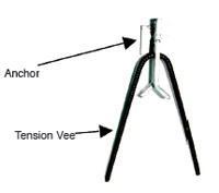
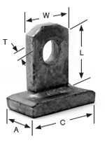
TWO HOLE ANCHOR
Lower hole accommodates rebar V's which are required to develop the SWL. Use only in tension. |
 |
| 2.5 |
FTH02.5040 |
102 |
50 |
16 |
10 |
32 |
1814 |
7257 |
| 2.5 |
FTH02.5028 |
70 |
27 |
14 |
10 |
32 |
1814 |
7257 |
| 5 |
FTH05040 |
102 |
48 |
16 |
16 |
38 |
3628 |
14514 |
| 5 |
FTH05055 |
140 |
76 |
17 |
16 |
38 |
3628 |
14514 |
| 10 |
FTH10070 |
178 |
89 |
25 |
20 |
64 |
7257 |
29029 |
| 22 |
FTH22118 |
298 |
156 |
38 |
25 |
79 |
19958 |
79832 |
|
|
| |
 |
|
|
Concrete Strength [] |
| Nominal System Capacity |
Rebar Size |
15 |
20 |
27 |
35 |
41 |
|
|
Length of rebar before bending [mm] |
| 2.5 Ton |
10 |
787 |
635 |
558 |
482 |
457 |
| 5 Ton |
12 |
1041 |
838 |
736 |
660 |
609 |
| 7.5 Ton |
16 |
1295 |
1066 |
914 |
812 |
736 |
| 10 Ton |
19 |
1549 |
1270 |
1092 |
990 |
889 |
| 22 Ton |
29 |
2895 |
2362 |
2057 |
1828 |
1676 |
|
|
| |
SPREAD ANCHOR
Used for both stripping and erecting.
With proper edge distances can be
pulled in any direction. |
 |
|
| 2.5 |
FSP02.5121 |
121 |
32 |
5 |
70 |
None |
None |
907 |
3628 |
| 2.5 |
FSP02.5102 |
102 |
32 |
10 |
70 |
None |
None |
1147 |
7257 |
| 2.5 |
FSP02.5140 |
140 |
32 |
10 |
70 |
None |
None |
1814 |
7257 |
| 5 |
FSP050102 |
102 |
38 |
13 |
85 |
None |
None |
1211 |
10886 |
| 5 |
FSP050121 |
121 |
38 |
13 |
85 |
95 |
22 |
1628 |
10886 |
| 5 |
FS 050171 |
171 |
38 |
13 |
85 |
95 |
22 |
2249 |
14514 |
| 5 |
FSP050159 |
159 |
38 |
16 |
85 |
95 |
17 |
2653 |
14514 |
| 5 |
FSP050241 |
241 |
38 |
16 |
85 |
95 |
17 |
3628 |
14514 |
| 7.5 |
FSP7.5279 |
279 |
64 |
16 |
133 |
127 |
25 |
5443 |
21772 |
| 10 |
FSP10286 |
286 |
64 |
20 |
133 |
127 |
25 |
7257 |
29029 |
| 22 |
FSP22387 |
387 |
95 |
25 |
159 |
229 |
35 |
14877 |
61688 |
| 22 |
FSP22479 |
479 |
95 |
25 |
159 |
330 |
35 |
19958 |
79832 |
|
|
| |
|
|
|
Concrete Strength [] |
| Nominal System Capacity |
Rebar Size |
15 |
20 |
27 |
35 |
41 |
|
|
Length of rebar before bending [mm] |
| 2.5 Ton |
10 |
787 |
635 |
558 |
482 |
457 |
| 5 Ton |
12 |
1041 |
838 |
736 |
660 |
609 |
| 7.5 Ton |
16 |
1295 |
1066 |
914 |
812 |
736 |
| 10 Ton |
19 |
1549 |
1270 |
1092 |
990 |
889 |
| 22 Ton |
29 |
2895 |
2362 |
2057 |
1828 |
1676 |
|
|
| |
ERECTION HEAD ANCHOR
Ideal for lifting in shear position, such as
a tilt table or A-frame. Rebar V’s are
required to develop SWL.
Available w/shear plate on request. |
 |
|
| 2.5 |
F EH 02 043 |
108 |
50 |
10 |
46 |
35 |
57 |
29 |
14 |
1814 |
7257 |
| 2.5 |
F EH 02 043 S |
108 |
50 |
10 |
46 |
35 |
57 |
29 |
14 |
1814 |
7257 |
| 2.5 |
FEH 02 080 |
200 |
50 |
10 |
46 |
35 |
57 |
29 |
14 |
1814 |
7257 |
| 5 |
F EH 04 075 |
189 |
64 |
16 |
64 |
46 |
81 |
32 |
20 |
3628 |
14514 |
| 5 |
F EH 04 075 S |
189 |
64 |
16 |
64 |
46 |
81 |
32 |
20 |
3628 |
14514 |
| 5 |
F EH 04 105 |
267 |
64 |
16 |
64 |
46 |
81 |
32 |
20 |
3628 |
14514 |
| 10 |
F EH 06 133 |
337 |
95 |
16 |
79 |
62 |
102 |
44 |
25 |
5443 |
21771 |
| 10 |
F EH 08 133 |
337 |
95 |
20 |
79 |
62 |
102 |
44 |
25 |
7257 |
29029 |
|
| |
|
 |
|
|
Concrete Strength [] |
| Nominal System Capacity |
Rebar Size |
15 |
20 |
27 |
35 |
41 |
|
|
Length of rebar before bending [mm] |
| 2 Ton |
10 |
9448 |
7620 |
6705 |
5791 |
5486 |
| 4 Ton |
12 |
12496 |
10058 |
8839 |
7924 |
7315 |
| 6 Ton |
16 |
15544 |
12192 |
10972 |
9753 |
8839 |
| 8 Ton |
19 |
18592 |
15240 |
13106 |
11887 |
10668 |
|
|
| |
FLAT FOOT ANCHOR
Ideal for back stripping or lifting thin precast panels. |
 |
| 2.5 |
F FA 02 028A |
70 |
32 |
5 |
102 |
907 |
3628 |
| 2.5 |
F FA 02 034A |
85 |
32 |
5 |
102 |
907 |
3628 |
| 2.5 |
F FA 02 028B |
70 |
32 |
10 |
102 |
1814 |
7257 |
| 2.5 |
F FA 02 034B |
85 |
32 |
10 |
102 |
1814 |
7257 |
| 5 |
F FA 04 038 |
95 |
38 |
13 |
102 |
2721 |
10886 |
| 10 |
F FA 08 063 |
159 |
64 |
16 |
152 |
5443 |
21772 |
|
|
 |
Reinforced Tension Loads require the use of additional rebars positioned as shown over the feet of the anchor.
For 2 ton anchors, use 2 x 12 mm rebars x 304 mm long each direction.
For 4 and 8 Ton anchors, use 2 x 12 mm rebars x 457 mm long each direction.
Maintain at least 20 mm cover underneath the feet of the anchor. |
|
| |
PLATE ANCHOR
Bottom plate allows high strength for stripping and erecting.
Reinforcement required to develop SWL. |
 |
| 2.5 |
F PA 02 023 |
57 |
32 |
10 |
95 |
32 |
1814 |
7257 |
| 5 |
F PA 04 030 |
76 |
38 |
13 |
76 |
38 |
3628 |
14514 |
| 5 |
F PA 04 035 |
89 |
38 |
13 |
76 |
38 |
3628 |
14514 |
| 5 |
F PA 04 044 |
111 |
38 |
16 |
98 |
38 |
3628 |
14514 |
| 10 |
F PA 08 071 |
181 |
60 |
20 |
32 |
64 |
4535 |
18143 |
|
|
|
Reinforced Allowable Tension Capacities
are with crossed 12 mm rebars x 457 mm long and
254 mm minimum edge distance. |
|
| |
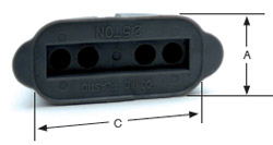
RUBBER RECESS FORMER
Reusable recess member. When attached to holding plate, allows positioning and handling of anchor.
 |
| 2.5 |
F PRF 02 |
43 |
44 |
103 |
10 |
| 5 |
F PRF 04 |
54 |
59 |
132 |
16 |
| 10 |
F RR 08 |
79 |
59 |
198 |
20 |
| 22 |
F RR 22 |
116 |
117 |
249 |
20 |
|
|
| |
| |
MAGNETIC RUBBER RECESS FORMER
To attach flat steel anchors to steel forms.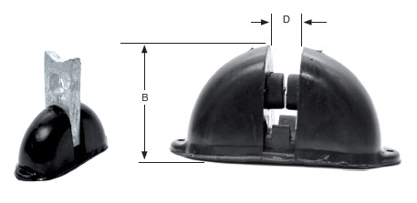 |
|
|
| |
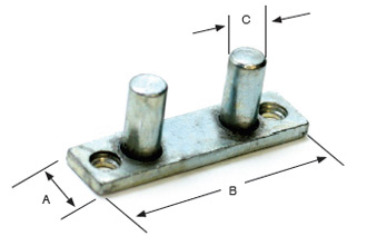
HOLDING PLATE
May be attached to form by nail holes, screw holes, or welding. Used to hold recess former. |
 |
| 2.5 |
F PRF 02 |
16 |
70 |
10 |
| 5 |
F PRF 04 |
32 |
85 |
10 |
| 10 |
F RR 08 |
44 |
124 |
12 |
| 22 |
F RR 22 |
64 |
178 |
16 |
|
|
| |
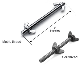
WING NUT & BOLT ASSEMBLY
Used to attach recess
former to form. |
 |
| 2.5 |
F WN 02 |
152 |
M8 |
| 5 |
F WN 04 |
152 |
M8 |
| 10 |
F WN 08 |
152 |
M12 |
| 22 |
F WN 22 |
152 |
M12 |
|
|
|
|
|
|
| |
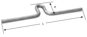
SHEAR BAR
Used with flat steel erection anchor to increase shear capacity. |
| 2.5 |
F SB 02 |
13 |
102 |
64 |
352 |
| 5 |
F SB 04 |
13 |
140 |
97 |
352 |
| 10 |
F SB 08 |
13 |
191 |
125 |
352 |
|
|
 |
|
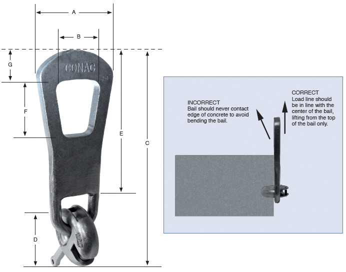
RING CLUTCH
W/ BAIL
Designed to be used specifically for flat steel lifting.
Handle allows for safe locking of clutch into lifting position. |
| 2.5 |
F RC 02 B |
92 |
54 |
267 |
76 |
178 |
70 |
32 |
| 5 |
F RC 04 B |
114 |
67 |
327 |
102 |
216 |
89 |
38 |
| 10 |
F RC 08 B |
140 |
76 |
432 |
149 |
264 |
114 |
44 |
|
|
 |
| |
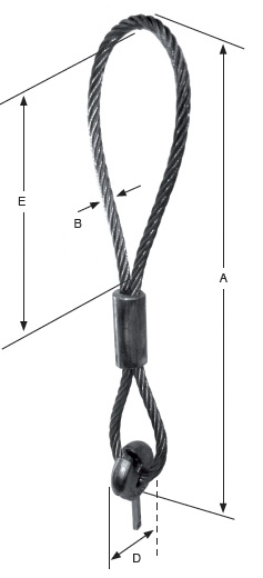
RING CLUTCH W/CABLE
Designed to be used specifically for flat steel lifting. Cable is more flexible than bail allowing some lattitude in the direction of lift.
Handle allows for a more safe locking of clutch into position. |
| 2.5 |
F RC 02 |
597 |
14 |
60 |
305 |
| 5 |
F RC 04 |
648 |
18 |
85 |
305 |
| 10 |
F RC 08 |
787 |
22 |
95 |
305 |
|
|
 |
CARE, INSPECTION AND MAINTENANCE OF RING CLUTCHES
(FOR BOTH STEEL BAILE AND CABLE BAILE)
CONAC Flat Steel System Ring Clutches may become worn after extended use or may be damaged through misuse, overloading, or a number of other factors, any one of which may affect the Safe Working Load of the Ring Clutch.
Responsible users will establish a system of periodic inspections which should include the following:
1. Inspect for general condition and wear.
2. Assure that the bail is free to rotate in all directions.
3. If the bail is bent or twisted, the clutch must be destroyed.
4. Check the curved bolt for wear, cracking or binding.
5. Check the clutch body for wear, cracking or deformation.
6. If it appears that the Ring Clutch has been heated in any way, the clutch must be destroyed.
Destroy any unit that is worn, damaged, bent or twisted by cutting off the bail. No repair or welding is permitted.
ADDITIONAL INSPECTION OF CABLE BAILES
1. Inspect cable for general condition and wear.
2. Check cable for nicks, kinks, crushing or bends.
3. Check for frayed or loose outer strands.
4. Check for cable swelling.
If the cable is damaged, the Ring Clutch must be destroyed
as above. |
|
| |
 |
| |